• +1 (830) 625-7923
  • 310 FM 483, New Braunfels, TX 78130
  • Mon - Fri: 8am - 5pm

AIRCRAFT PROP GOVERNORS

A prop governor is a device which automatically adjusts the angle of the aircraft propeller blade as necessary to maintain a constant engine speed under varying flight conditions. The range of adjustment of the prop governor is limited only by the blade angle range of the propeller. There are many different designs of prop governor, and we’ll cover them here in this article.

For the ease of explanation, we will be using Hamilton Standard prop governors as a reference. However, the prop governors produced by Hartzell, McCauley, Woodward, Curtis, and may other manufacturers all essentially operate on the same basis.

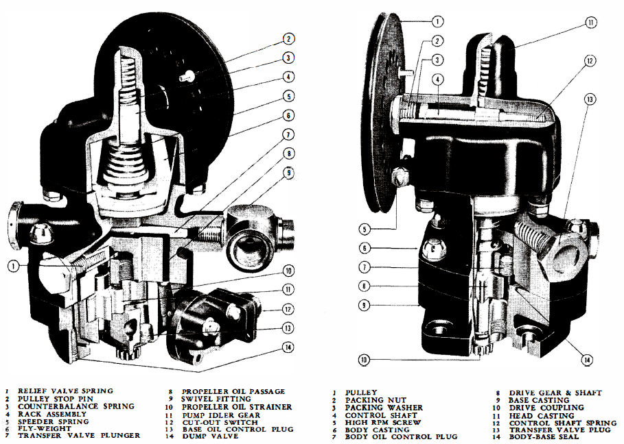
A prop governor mainly consists of:

  • A gear pump which is responsible for boosting oil provided from the engine lubricating system to the pressure required to operate the propeller pitch change mechanism,
  • A pilot valve actuated by a spring balanced fly-weight which controls the flow of oil to and from the propeller,
  • A relief valve which limits the output pressure of the gear pump, and
  • A pulley which regulates the compression of the spring.

Prop governors come in various types, but there are three general types used on aircraft: Counterweight, Hydromatic and Double-Acting Hydromatic

Counterweight Prop Governor

COUNTERWEIGHT

In order to understand the operation of a counterweight prop governor, it is necessary to have a basic understanding of the counterweight propeller. The counterweight propeller changes pitch by the use of two forces; centrifugal force caused by counterweights fastened to the blades, and an opposing force provided by the hydraulic piston-cylinder. The piston-cylinder is designed in such a way that when oil is forced into the piston chamber, the cylinder moves outward on the piston and turns the propeller blades towards low pitch.  The oil used to move the cylinder is metered to the propeller by the prop governor.

If the engine speed drops below the on-speed RPM, the rotational force on the fly-weight in the prop governor becomes less allowing the speeder spring to move the pilot valve downward. When the pilot valve is in the downward position, oil from the gear pump flows from the prop governor to the propeller moving the cylinder outward. This causes a decrease in propeller blade angle and reducing the drag caused by air through the propeller allowing the engine to increase in speed until the engine returns to the on-speed setting.

If the engine speed increases above the on-speed RPM, the rotational force on the fly-weight in the prop governor becomes more which compresses the speeder spring moving the pilot valve upward. When the pilot valve is in the upward position, oil from the propeller cylinder is allowed to flow back through the prop governor drain allowing the cylinder to move inward caused by the centrifugal force of the counterweights. This causes an increase in propeller blade angle which increases the drag caused by air moving through the propeller and causes the engine to decrease in speed until the engine returns to the on-speed setting.

When the engine speed matches the speed set on the prop governor, this is the on-speed condition. This causes the balancing of the forces of the flyweight and the speeder spring which positions the pilot valve so that oil is neither supplied to or drained from the propeller piston-cylinder causing the angle of the propeller blades to remain fixed in position. The RPM setting of the prop governor is made by varying the position of the pulley.

SINGLE-ACTING HYDROMATIC

In order to bet a better understanding of the hydromatic propeller governor, it is advantageous to first understand the operating principals of the Hydromatic type propeller. The Hydromatic propeller is an oil actuated constant speed and full feathering propeller which is regulated by means of the engine driven prop governor. The propeller pitch change mechanism consists of a piston operating in a cylinder and connected to the propeller blades through cams and gears. The piston is move inboard and outboard by oil pressure, which decreases and increases the blade angle. In order to maintain constant engine speed at any RPM, the governor supplies and controls the flow of oil to and from the propeller.

Single-acting hydromatic prop come in three different types: single capacity, double capacity and accumulator types. The basic operation is as follows: if the engine speed drops below the speed for which the prop governor is set, the rotational speed of the fly-weights decreases and the speeder spring moves the pilot valve downward allowing oil to drain from the propeller allowing the blade angle to decrease causing the engine to return to the on-speed setting. If the engine speed rises above the speed for which the prop governor is set, the rotational speed of the fly-weights increases and the speeder spring moves the pilot valve upward permitting oil to flow from the governor pump to the propeller causing the blade angle to increase slowing the engine so that it returns to the on-speed setting. During on-speed operation, the pilot valve is is in a neutral position where oil neither drains or is supplied to the propeller. The RPM setting of the governor can be changed by varying the compression of the speeder spring through rotation of the control wheel.

Unlike the Counterweight type prop governor, the Hydromatic prop governor can include a pressure-operated transfer valve, which on feathering installations, allows high pressure oil from an auxiliary pump to shunt out or add to the governor output when the propeller is being feathered or unfeathered. Feathering of the propeller becomes useful in the event of an issue where the engine must be shutdown. Feathering causes the propeller blades to rotate along its longitudinal axis until the blades are flat, preventing the propeller from grabbing air as the aircraft is flying which would cause it to rotate and would cause the engine to rotate which could cause more damage to the engine.

Single Capacity
The single capacity prop governor is used on aircraft requiring an average rate of propeller pitch change, and with blade and propeller designs requiring reasonably low governing pressures.

Double Capacity
The double capacity prop governor is used on aircraft requiring a higher rate of propeller pitch change, and has higher governing pressures needed for pitch change of propellers with larger blade areas.

Accumulator
The accumulator governor is usually installed on highly maneuverable aircraft which require the accumulator feature. The accumulator is a separate storage tank, connected to the governor, which holds oil under pressure to compensate for the momentary loss of engine oil cause by brief periods of negative gravitational acceleration. You can learn more about accumulators here.

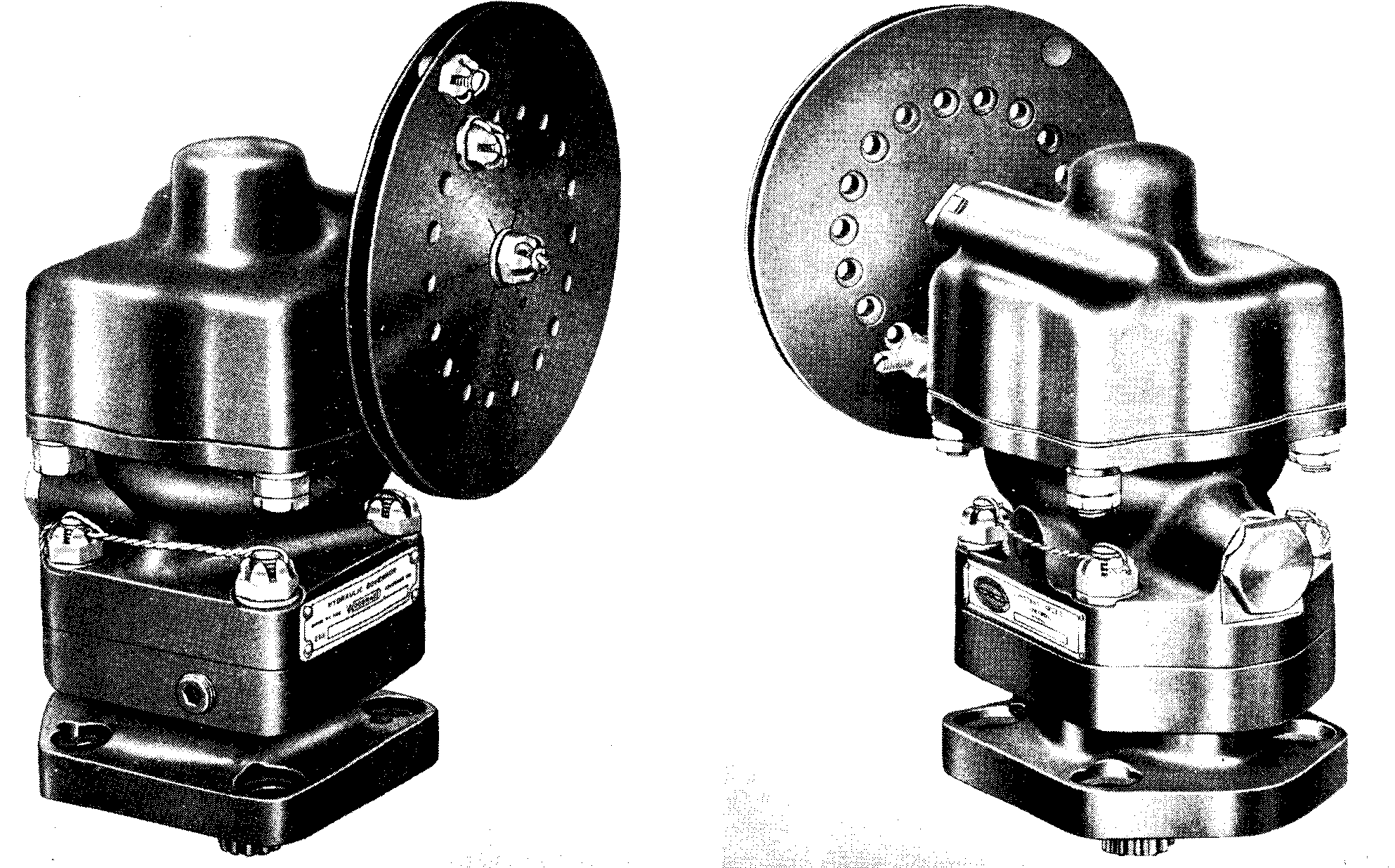
Hydromatic Prop Governor Cutaway
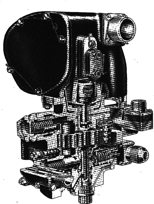
Double-Acting Prop Governor Cutaway

DOUBLE-ACTING HYDROMATIC

Operation of the double-acting governor is very similar to that of the single-acting hydromatic prop governor except that the pump output oil can be directed to either the inboard or outboard side of the the propeller piston. Oil returning from the propeller is directed to the intake side of the pump and is used over aging. During the underspeed condition, oil from the gear pump moves to the outboard side of the propeller piston. This causes the blades to move to a lower pitch, and the governor returns to an on-speed condition. In the on-speed condition, both lines to the propeller are closed off by the pilot valve resting in its neutral position. In an overspeed condition, the pilot valve is raised allowing oil to enter the inboard side of the propeller, causing the blades to move to a higher pitch allowing the governor to return to an on-speed condition.

Some models of double-acting prop governors have the ability to reverse the propeller. Reversing the propeller causes it to rotate along it’s longitudinal axis until the blade angle is in a negative position. This causes the propeller to provide reverse thrust. The use of a reversible propeller and prop governor makes it possible to shorten the landing run and improve ground maneuverability of the aircraft, as well as backing the aircraft up.

GOVERNOR MAINTENANCE

Prop governor maintenance is very simple and can be accomplished in a few easy steps:

  1. Visually examine the prop governor seams, nuts a and sealing surfaces for evidence of oil leaks or damage to mounting surface. Leaks are present when oil is visible on the outside of the prop governor. Oil color can be amber, grey or black.
  2. Check for proper operation of the unit in accordance with the aircraft manual.
  3. Service Life or the maximum operating time between overhauls is the same as the propeller and should be overhauled along with the propeller, unless the aircraft maintenance manual states otherwise.

If any of the checks failed, the prop governor should be immediately removed and sent for overhaul or repair.

© Copyright 2024 S & T Aircraft Accessories, Inc.