• +1 (830) 625-7923
  • 310 FM 483, New Braunfels, TX 78130
  • Mon - Fri: 8am - 5pm

HYDRAULIC AIRCRAFT ACCUMULATORS

A hydraulic accumulator is a device, typically made of steel, which is divided into two separate chambers. One chamber is charged to a high pressure with air or nitrogen, while the other chamber contains fluid at the system operating pressure. Most aircraft have several hydraulic accumulators, one operates the main hydraulic system, one for the emergency system, and others are used for various other systems.

Accumulators have various functions, some of these functions include:

  • Dampen rapid fluid and pressure changes in the hydraulic system.
  • Assist the hydraulic pump in times of demand to help maintain pressure in the hydraulic system.
  • Store power in the form of pressure, for use in emergencies to operate hydraulic components when the pump is not operating.
  • Supply pressurized fluid for compensation of undesired internal or external leakage that would cause pump cycling or surging.

Accumulators come in various types, but there are two general types used on aircraft: spherical and cylindrical.

Spherical Accumulator Operation
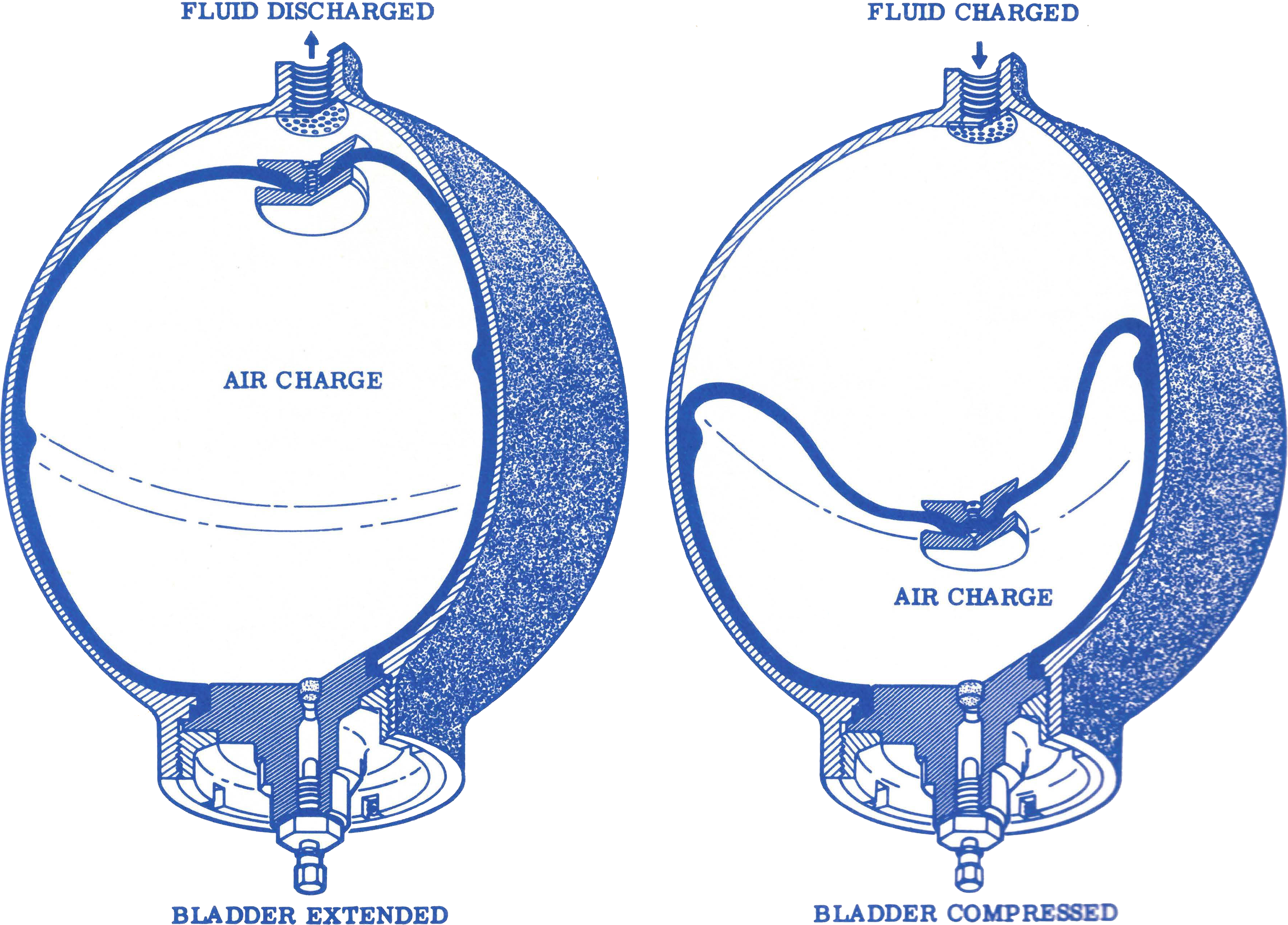
A spherical accumulator with a bladder showing operation of the accumulator.

SPHERICAL ACCUMULATORS

The spherical hydraulic pressure accumulator is a pressure vessel containing a non-compressible hydraulic fluid and a compressible gas, normally air or nitrogen with which the unit is pre-charged. A flexible bladder or diaphragm prevents loss or transfer of either air or fluid, maintaining both the air and fluid at equal pressures. As fluid enters through the fluid port, the bladder or diaphragm compresses the air in the accumulator. When demand is made upon the hydraulic system, the compressed air forces the fluid out of the accumulator.

CYLINDRICAL ACCUMULATORS

Cylindrical hydraulic accumulators operate on the same principals as the spherical accumulator. They consist of a cylinder with two threaded end caps and a piston assembly. The piston assembly separates the hydraulic fluid from the air/nitrogen chamber. The end caps are sealed with gaskets and seals to prevent external leakage around the end caps. The piston is sealed internally with double seal rings to prevent internal leakage of fluid into the air chamber.

Cylindrical Accumulator Operation
A cylindrical accumulator with a piston showing operation of the accumulator.

ACCUMULATOR OPERATION

Spherical and cylindrical accumulators operate in essentially the same manner. In operation, the air chamber is charged to a pressure lower than that of the system operating pressure. This initial charge is referred to as the pre-charge. To illustrate operation, let’s use the cylindrical accumulator as an example.

Let’s assume the accumulator is pre-charged to 1,500 PSI and will operate in a hydraulic system where the operating pressure is 3,500 PSI. When the pre-charge of 1,500 PSI is applied to the accumulator, and the system pressure is at zero, the piston will actuate to the fluid end of the cylinder. Because the pre-charge is 1,500, the hydraulic system will need to generate a pressure greater than 1,500 PSI before the hydraulic fluid can enter the accumulator causing the piston to move backwards.

As hydraulic fluid fills the cylinder it causes the piston to move backwards compressing the air in the air chamber. At 2,500 PSI, the piston will have backed up several inches, and at 3,500 PSI the piston will be in it’s normal operating position compressing the air until it occupies less than half of the cylinder. It is the natural tendency of the unit to maintain equal pressure on both the fluid side and the air side of the cylinder. As the system pressure increases it pushes the piston back to compress the air which also increases the air pressure, until the air pressure is equal to that of the system pressure.

When the use of hydraulic units lower the system pressure, the pressure on the fluid side of the accumulator will decrease and the higher pressure on the air side will force the piston forward expelling hydraulic fluid from the accumulator to provide fluid for the increase in demand on the hydraulic system.

Many aircraft make use of several accumulators in the  hydraulic system. Typically there will be one installed in the main hydraulic system and one in the emergency hydraulic system. There can also be auxiliary accumulators that operate other aircraft systems. Regardless of the number, type and location in the system, all accumulators perform the same function: storing extra hydraulic fluid under pressure, and providing that fluid in times of peak demand or emergency.

ACCUMULATOR MAINTENANCE

Accumulator maintenance is very simple and can be accomplished in a few easy steps:

  1. Visually examine the accumulator for evidence of fluid leaks. Leaks are present when hydraulic fluid is visible on the outside of the accumulator. Hydraulic fluid can be amber, red, green or purple in color. For an oil system it can be amber, grey or black.
  2. Examine the accumulator for evidence of air leaks by brushing soapy water on the outside. Bubbles will develop where an air leak is present.
  3. Check for internal fluid leakage by loosening the air valve. If fluid comes out, either in a mist or stream, the unit should be removed and sent for repair.
  4. Check the pre-charge pressure after releasing the hydraulic system pressure. Many accumulators on aircraft are equipped with air pressure gauges for this purpose. When a pressure gauge is not equipped, a high-pressure gauge may be installed at the air pre-charge fitting for this purpose. The required pressure will be stated in the manual for each aircraft.

If any of the checks failed, the accumulator should be immediately removed and sent for overhaul or repair. When removing the unit for repair, be sure to completely relieve the system pressure first, then completely relieve the air pressure.

© Copyright 2024 S & T Aircraft Accessories, Inc.